EPC Interconnection LNG Pipeline Hot Tapping Installation GCP Project Ghana
No Pics.
EPC Interconnection LNG Pipeline Hot Tapping Installation GCP Project Ghana
On April 2nd, ZHM Metal Engineering Co.,Ltd. and Zhejiang Huawu Steel Structure Engineering Co.,Ltd. has been honorably awarded and signed for the Phase II of the EPC Contract Agreement-Interconnecting GCP LNG Pipeline Project, Ghana after our successful construction of the Phase I during 2020-2023. With our existing fixed assets invested in Ghana local areas for the past one decades, we have the confidence to complete this new project timely and successfully for our old customer.
We, as the EPC contractor, are taking the responsibility as the following matrix:
| Project Schedule-GCP Interconnection Pipeline & Hot Tapping | |||||
| Product | Task Name | Start Time | Calendar Days | Completion Time | Remarks |
|
GCP Interconnection Pipeline & Hot tapping DN300 |
Total lead time of GCP Interconnection Pipeline & Hot tapping Project |
20/03/2024 | 90 | 20/06/2024 |
The Estimated Start Time will be 20th Mar.2024 and Subject to the Effective of Final EPC Contract. |
| 1 |
ROW Pipeline Design &Hop Tapping Design 作业带管道设计 和带压开孔设计 |
20/03/2024 | 20 | 10/04/2024 | EPC Contractor |
| 2 |
ROW Pipeline Design &Hop Tapping Design Basic Design 作业带管道基础设计 和带压开孔基础设计 |
20/03/2024 | 15 | 05/04/2024 | EPC Contractor |
| 3 |
ROW Pipeline Design &Hop Tapping Design Detailed Design 作业带管道详细设计 和带压开孔详细设计 |
20/03/2024 | 20 | 10/04/2024 | EPC Contractor |
| 4 |
Temporary Cathodic Protection System Design 临时阴极保护设计 |
20/03/2024 | 20 | 10/04/2024 | EPC Contractor |
| 5 |
Procurment and Fabrication of Installation Material / Equipment 安装材料/设备的采购和加工 |
20/03/2024 | 45 | 05/05/2024 |
1. Pipeline Installation material/Equipment 20 days. EPC Contractor 2. Hop tapping Basic Installation Material/Equipment Needs to be Fabrication, which will take 45 days. EPC Contractor(Note: if procurment of extra valves, spendings will be responsed by Employer.) 1.管线安装材料/设备 20天 承包商负责 2. 带压开孔基本安装材料设备需要生产制作,需要45天(如需要额外的阀门,费用由建设方负责) 承包商负责 |
| 6 |
Shippment of Installation Material /Equipment 安装材料/设备的发运 |
31/03/2024 | 75 | 15/06/2024 |
According to the construction reality on site, Partial shippment will use airlift. EPC Contractor 根据现场的实际情况,部分采用空运 承包方负责 |
| 7 |
Supply of Pipes and Bends to the PSAs 管子和弯头的供应 |
Employer |
|||
| 8 |
ROW Preparation shall be Completed 10 days earlier thanthe commencement of installation 安装前10天作业带准备 |
Employer | |||
| 9 |
20'' Pipeline Installation 20寸管道安装 |
10/04/2024 | 50 | 01/06/2024 | EPC Contractor |
| 10 |
12'' Pipeline Installation 12寸管道安装 |
20/05/2024 | 20 | 10/06/2024 | EPC Contractor |
| 11 |
Hot Tapping 带压开孔 |
05/06/2024 | 10 | 15/06/2024 | EPC Contractor |
| 12 |
Documents Handing over 提交资料 |
20/03/2024 | 90 | 20/06/2024 | EPC Contractor |
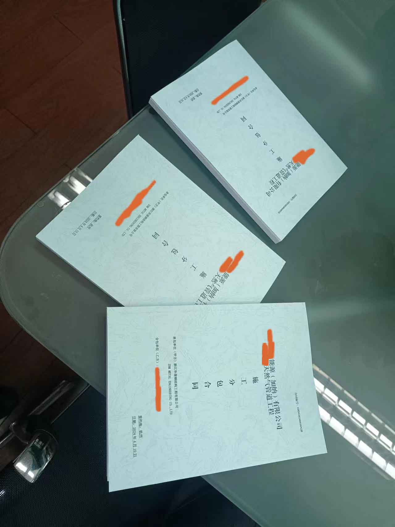
Interconnecting GCP Interconnection LNG Pipeline Hot Tapping Installation Project: Contract Signing

Interconnecting GCP Interconnection LNG Pipeline Hot Tapping Installation Project: Site Construction Manager Ghana Honorary Chief Title Award
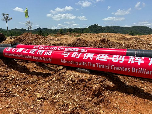
Interconnecting GCP Interconnection LNG Pipeline Hot Tapping Installation Project: Commence of first welding seam Ceremony Activities
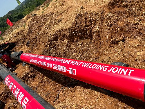
Interconnecting GCP Interconnection LNG Pipeline Hot Tapping Installation Project: Commence of first welding seam Ceremony Activities
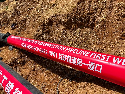
Interconnecting GCP Interconnection LNG Pipeline Hot Tapping Installation Project: Commence of first welding seam Ceremony Activities
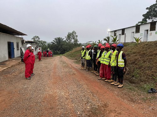
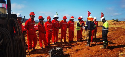
Interconnecting GCP Interconnection LNG Pipeline Hot Tapping Installation Project: Site Morning Construction Meeting
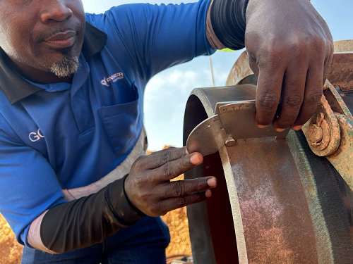
Interconnecting GCP Interconnection LNG Pipeline Hot Tapping Installation Project: Pipe Material Bevel Cutting Inspection
Interconnecting GCP Interconnection LNG Pipeline Hot Tapping Installation Project: Site Morning Construction Meeting
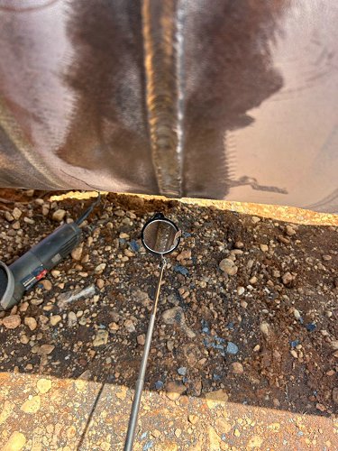
Interconnecting GCP Interconnection LNG Pipeline Hot Tapping Installation Project: First Butt Welding NDT Testing
Interconnecting GCP Interconnection LNG Pipeline Hot Tapping Installation Project: First Butt Welding NDT Testing
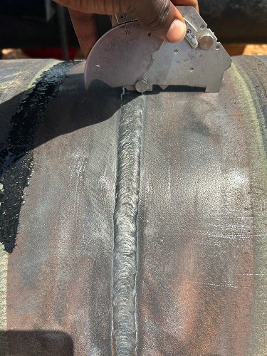
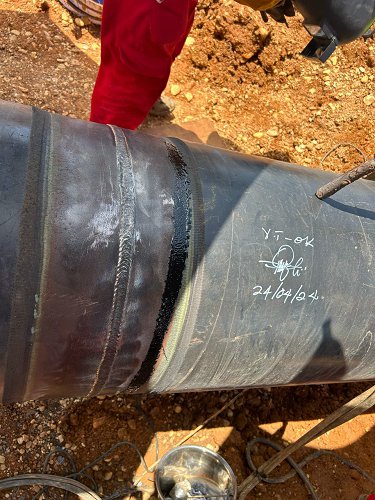
Interconnecting GCP Interconnection LNG Pipeline Hot Tapping Installation Project: First Butt Welding Size and NDT Testing
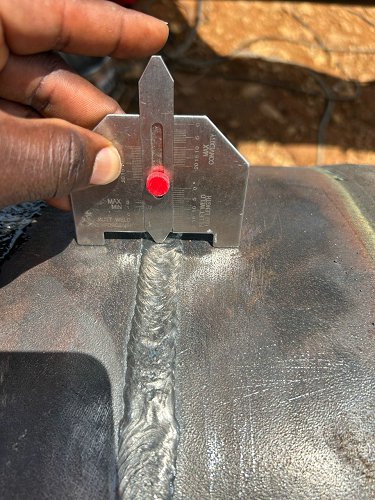
Interconnecting GCP Interconnection LNG Pipeline Hot Tapping Installation Project: First Butt Welding Size and NDT Testing
Interconnecting GCP Interconnection LNG Pipeline Hot Tapping Installation Project: Site Later afternoon meeting
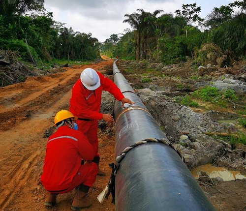
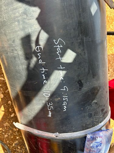
Interconnecting GCP Interconnection LNG Pipeline Hot Tapping Installation Project: Installation and welding ongoing: Construction team welding inspection
Interconnecting GCP Interconnection LNG Pipeline Hot Tapping Installation Project: Installation and welding ongoing: Pressure Testing
Interconnecting GCP Interconnection LNG Pipeline Hot Tapping Installation Project: Connection to Existing Tanks
Interconnecting GCP Interconnection LNG Pipeline Hot Tapping Installation Project: Connection to Existing Tanks
Interconnecting GCP Interconnection LNG Pipeline Hot Tapping Installation Project: Connection to Existing Tanks
Milestone Values
|
# |
Tranche |
Section Description |
Size/Spec |
Distance/Length |
Working Package |
Milestone Amount |
Milestone Terms |
|
1 |
|
Engineering Design and Procurement |
|
|
Engineering and Procurement |
|
1. Completion of Engineering and EPC Contractor’s Personnel arrival on site .
2. 1. Completion of the Supply and delivery of installation material(excluding pipes and bends) |
|
2 |
|
12” BP01 with GRRS-49 12” gas connection |
12" |
2.5KM |
|
|
1. Mechanical, Civil, Electrical and Controls work(Cable Laying) Completion and Sign off by SGS(Third party Inspector) |
|
3 |
|
Internal Bypass inside GRRS-49 |
6" |
6.5 M |
Construction |
1. Mechanical, Civil, Electrical and Controls work(Cable Laying) Completion and Sign off by SGS(Third party Inspector)
|
|
|
4 |
|
Hot Tapping Works |
|
|
|
|
1. Completion of the Supply and delivery of installation material(excluding pipes and bends) 2. Mechanical, Civil, Electrical and Controls work(Cable Laying) Completion and Sign off by SGS(Third party Inspector)
|
|
5 |
|
20” pipeline from PRMS-24 to GCP (Piggable pipeline) |
20" |
6KM |
|
|
1. Mechanical, Civil, Electrical and Controls work(Cable Laying) Completion and Sign off by SGS(Third party Inspector)
|
|
6 |
|
New 20” piggable pipeline from GCP to GRRS-49 |
20” |
6KM |
|
|
1. Mechanical, Civil, Electrical and Controls work(Cable Laying) Completion and Sign off by SGS(Third party Inspector)
|
|
7 |
|
2 new 20” pipeline at Ankobra River |
20" |
|
|
|
1. Completion of the Supply and delivery of installation material(excluding pipes and bends) 2. Mechanical, Civil, Electrical and Controls work(Cable Laying) Completion and Sign off by SGS(Third party Inspector) 3. |
|
8 |
|
Commissioning and Final Documentation |
|
|
Commissioning |
|
1. Completion and commissioning of Pipeline. 2. Completion Certificate Sign off by Employer’s representative. 3. Final documentation submission and issue of Quality Warranty Bond(QWB) 4. Employer’s claims payment QWB shall remain valid and enforceable until the Performance Certificate has been signed off by the Employer’s Chief Executive Officer. |
|
9 |
100% |
|
|
|
|
|
|
Purpose of Works
Energy has commissioned more than 400 Km of Natural Gas Pipeline and they are currently in successful operation. The current scheme of operation is such that the Lean Gas feed to Existing pipeline systems is from 2 outlet points: PRMS-24 send gas through BP01 12” pipeline and PP01 20” pipeline via GRRS-49. After startup and certification of Products for the New Gas Processing Plant at Prestea (GCP), the scheme of operation will change to:
PRMS-24 serving as the only gas source sending all the Lean Gas to GCP and the Natural Gas production coming from top of Demethanizer which is now of better quality will be fed to GRRS-49, from GRRS-49 the PP01 will feed at 100 Barg Design Pressure (commonly expected around 85 Barg) and these pressures will be regulated down to stable conditions to BP01 (at around 65 Barg). To achieve this, the following activities must be carried out.
A. Connection of 12” BP01 with GRRS-49 12” gas connection: The current available outlet at GRRS-49 from PL-4902 will be connected in piggable routing with the BP01 which is currently feeding gas either Takwa, Damang or Wassa Plants. The new route will be piggable, but the connection or tie-in to BP01 shall be by applying Hot-Tap 12”-to-12 special technique, basically due to the prevalence of No-Shut-down of all the 3 Power Plants mentioned before.
B.
C. Installation of Internal Bypass inside GRRS-49: this will permit Employer to receive gas from BP01 to feed all the PP01 line connections: The Employer’s Edikan and Chirano Plants, as well as Ejisu BMS-50.
D.
E. Extension of 20” pipeline from PRMS-24 to GCP (Piggable pipeline): The existing 20” piggable pipeline connecting the PRMS-24 outlet to the GRRS-49 gas inlet needs to be interfered with to enable a 20” piggable pipeline extension/continuation to the GCP inlet. Also, to maintain the current connection to GRRS-49 from PRMS-24, there should be an installation of a barred tee. The barred end of the tee branch should be connected to the same existing inlet pipeline to GRRS-49. At the GRRS-49 where the new barred tee and bypass need to be installed, there should be a consideration for the installation of a new skid(s) with corresponding block valves in safe distances to the existing Vent Stack (relocation of Vent Stack could also be considered per recommendation). Also, the new skid(s) must be at a location which does not interfere with the route of the next item scope. The installation of 2 new Block valves on each end of the tee will guarantee an adequate permanent sealing of gas to enable the use of a single inlet line (inlet to GCP or GRRS) from PRMS-24 when needed. This new inlet pipe in 20” connected to the same in operation inlet will need to be above ground for safe operation, but the tie-in connection to the current route of 20” buried line is underground because the currently available 20” pipe is too short to connect a new piggable route. It shall also be factored into the design specifications the crossing of the Ankobra River for this new 20” gas feed line to GCP. This scope shall include the connection to the Inlet of Module 1 at GCP.
F.
G. New 20” piggable pipeline from GCP to GRRS-49: A new 20” piggable pipeline to connect the GCP gas Outlet (Natural Gas production delivery point) to the currently available 20”-600# pig receiving line at GRRS-49. This new piggable pipeline shall be installed at the same ROW of the previous scope item ; 20” pipeline extension. It shall also be factored into the design specifications the crossing of the Ankobra River for this new 20” gas delivery line from GCP. Please assume the 45º hot-bend fittings as the same specifications as the ones used at GRRS-49. This scope shall include the connection to the outlet of Module 1 at GCP.
H.
I. Provision for 2 new 20” pipeline at Ankobra River: 2 new 20” pipeline shall be installed across the Ankobra River with the same design specifications as the above scope for future application or usage. Items 3, 4 5 together might be referenced like ‘Permanent Mode of Operation’. This scope shall include the works for preservation of the buried under-river-bed lines as well as the adequate design installation at line both ends.
The purpose of the Works is to ensure the design, the execution and the completion of the GCP Interconnection Pipeline as specified in Appendix E. The EPC Contractor’s Scope of Works as specified below shall comply with the standards as specified in Schedule 14
Detailed engineering and installation for the pipes with specification below:
|
Pipe Size/ inch |
Distance/km |
|
20” |
12.00 |
|
12” |
3.012 |
|
6” |
0.012 |
Table 1:Sections, routes, pipe dimension and distance for Interconnection Pipeline
EPC Contractor’s Detailed Scope of Work
The EPC Contractor’s Scope of Work for the Interconnection Pipeline as summarized in Table 1 below includes but is not limited to:
1. Hot tapping works- D323.8×7.93mm API 5L X52M PSL2 coated with 3LPE,One point
2. Installation of Pipes and Bends including installation material but excludes the supply of the pipes and bends
3. Cathodic Protection System
i. Detailed engineering of temporary cathodic protection
ii. Construction, Testing and Commission of Permanent and Temporary cathodic protection.
iii. Cost, Insurance and Freight (CIF, Tema Port) of cathodic protection
4. Fiber Optic Cable
i. Cost, Insurance and Freight (CIF, Tema Port) of fiber optic cable.
ii. Construction, Testing and Commission of the fiber optic cable.
5. Cost, Insurance and Freight (CIF, Tema Port) of all installation material, tools and equipment for construction and installation of the various sections of pipeline route, cathodic protection, and fiber optic cable.
6. Pipe Trench Excavation and Backfilling
7. Employer will assist in clearing of all the installation material, equipment and tools. Employer shall pay custom clearing duty and shipping line charges for all material with total accumulative cost not more than usd X00,000.00. EPC Contractor shall pay custom clearing duty and shipping line charges for all materials, equipment and tools with total accumulative cost more than usd X00,000.00. EPC Contractor shall pay for the clearing duty cost and shipping line cost for all tools and equipment.
8. The EPC Contractor shall arrange the sand sack at the Temporal Pipe Storage area to receive the pipes.
9. Offloading of the pipes at Temporal Pipe Storage Area
10. EPC Contractor Construction scope shall include but not limited to welding,x-ray test, corrosion prevention, stringing of pipes on the right of way, pipe trench excavation, pipe lowering to trench, laying fiber optic cables, temporary and permanent cathodic protection installation, warning tape laying, pipe trench backfilling (first and second stage) including but not limited to ground grid installation, Testing which includes but not limited to Electrical Spark Test, Peel Test, Commissioning of the pipelines.
11. Installation, tie-in of all skids with pipeline and plant, Testing and Commission of station skids.
12. Development of Inspection Test Plan (ITP) and Installation Material Philosophy for the entire Interconnection Pipeline
13. Supply of a source of electricity power and its related fuel.
14. No more than X units of pipe jacking shall be delivered as part of the scope of work for the sections
15. No more than XX500 cbm of hydro-protection shall be delivered as part of the scope of work for the sections under the Interconnection Pipeline
16. Stone excavation work of not more than X,000 cbm. Extra Stone excavation works exceeding 5,000cbm shall be charged to Employer at $X0.00 per cbm.
17. The supply of Nitrogen for commissioning of the pipelines before operation is not in the scope of EPC Contractor but rather the Employer.
18. Visa, working permit, all necessary health test and flight for all workers.
19. Accommodation and welfare of EPC Contractor’s workers including water, sewage treatment etc.
The EPC Contractor shall undertake the following detailed Engineering, Procurement (installation materials) and
Construction of the Interconnection Pipeline as described below:
1. Engineering Designs and Documents of Pipeline Installation
|
Ø Civil Discipline |
||
|
C1 |
General Construction Specifications Pre-Commissioning and Commissioning |
|
|
C2 |
Key Plans |
|
|
C3 |
Cross Sections |
|
|
C4 |
Road Creeks and Rivers Crossings |
|
|
Ø Mechanical Discipline |
||
|
M1 |
Basis and Design Criteria |
|
|
M2 |
Construction Specifications |
|
|
M3 |
Paint Coating |
|
|
M4 |
Hydrostatic Pressure Test Specifications, Leakage Test Specifications |
|
|
M5 |
Supports Specifications (information required for Employer personnel for civil foundations and above ground structures) |
|
|
M6 |
Tie-Ins Specifications and Folder with Details |
|
|
M7 |
Welding Specifications (including Welding Maps) / Coating reestablishing for pipes and welding joints/ Lifting Plan for pipeline installation (partial weldings and lowering) |
|
|
M8 |
Material's List and Spare part List (including consumables) |
|
|
M9 |
N/A |
|
|
M10 |
Plant, elevation and details |
|
|
Ø Electrical Discipline |
||
|
E1 |
Design of cathodic protection by impress current including location of rectifiers, anodes measurement points and electrode of reference cathodic DC cables; welded connection to pipe and coating |
|
|
E2 |
Specification of equipment and materials including rectifier, anodes, measurement points, cathodic DC cables. |
|
|
E3 |
Power supply of Cathodic rectifiers (Design of AC electrical system) |
|
|
E4 |
Detailed drawings showing location of AC power supply per rectifier; routes and location of AC cables |
|
|
E5 |
Specification of equipment and materials |
|
|
1.6.1 |
Low voltage cables overground including distribution boards, conduits, cable schedules, etc. |
|
2. Procurement
i. Installation Materials for Pipeline (specification shall be as approved after the design), these include but not limited to sleeve coatings, paints, cables, welding electrodes and wires, interconnecting pipings.
3. Construction and Commission Scope of Pipeline
|
Ø Mechanical, Civil and Instrumentation discipline |
Remarks |
|
|
1 |
General Activities for the complete project |
|
|
1.1 |
Mobilization |
|
|
1.2 |
Provisional Buildings Installation |
|
|
1.3 |
Demobilization |
|
|
2 |
Natural Gas Pipeline |
|
|
2.1 |
Mechanical Activities |
|
|
2.1.1 |
Coated Pipeline transportation from each Pipe Storage Area (PSAs) to ROW |
|
|
2.1.2 |
20”and 12” (inch) piping fabrication, welding and Installation |
|
|
2.1.3 |
Fiber optic installation along the pipeline route in same trench |
|
|
2.1.4 |
NDT Test at pipeline welded joints |
Including X Rays |
|
2.1.5 |
Sleeve wraps(with adhesive) supply and installation |
In every underground welded joint |
|
2.1.6 |
20”and 12” (inch) Piping lowering into the trench |
|
|
2.1.7 |
Underground pipeline signings installation |
Every 250m. |
|
2.1.8 |
Pipeline fabrication for road and railway crossings |
|
|
2.1.9 |
Blind flange installation
|
At the beginning and the end of each pipeline(before and after the stations) |
|
2.1.10 |
Pipeline fabrication for short river crossings |
|
|
2.1.11 |
Road crossings execution with Pipe Jacking |
|
|
2.1.12 |
Pipeline protection casing installation at the road Crossings |
Including Covers and Separators |
|
2.1.13 |
Road crossings execution with trench excavation |
Including Pavement Repairs |
|
2.1.14 |
River crossings execution with trench excavation Water crossings execution with trench excavation
|
To prevent flooding of nearby farms and residence to the camps and right-of-way as a result of elevating the lands close by during construction |
|
2.1.15 |
Interconnections between skids, venting lines, drainage system (including Drainage Drum works). |
Works to be executed internal each Stations |
|
2.1.16 |
|
|
|
2.1.17 |
Second coating installation |
For Protecting the main pipeline coating at river Crossings |
|
2.1.18 |
Hydrostatic Test after pipeline fabrication and Installation |
According to ASME B31.8 Standard |
|
2.1.19 |
Functional operational tests |
|
|
Ø Electrical and Control discipline |
Remarks |
|
|
1 |
Cathodic protection system (along the complete pipeline route)
|
The design of permanent cathodic protection shall be the responsibility of the Employer(or his Station and Skids Sub EPC Contractor) |
|
1.1 |
Excavation for anodes |
|
|
1.2 |
Installation of anodes |
|
|
1.3 |
Back filling of anodes |
|
|
1.4 |
Installation of measurement points |
|
|
1.5 |
Excavation for electrode of reference |
|
|
1.6 |
Installation of electrode of reference |
|
|
1.7 |
Back filling for electrode of reference |
|
|
1.8 |
Trench excavation for DC cable |
|
|
1.9 |
Installation of DC cables |
|
|
1.10 |
Trench back filling for DC Cables |
|
|
1.11 |
Exothermic welded connection to the pipe (included coating) |
|
|
1.12 |
Installation of rectifiers |
|
|
1.13 |
Installation of measurement boxes |
|
|
1.14 |
Installation of distribution boards (AC) |
|
|
1.15 |
Installation of power cables for rectifiers in conduit |
|
|
1.16 |
Connection of rectifiers to AC power supply |
|
|
1.17 |
Connection in rectifiers to DC cables (anodes and pipes) |
|
|
1.18 |
Commissioning and final test |
|
|
2 |
Communication, monitoring and control system installation (fiber optic along the complete route) |
|
|
2.1 |
Installation of fiber optic (along the complete route) |
|
|
2.2 |
Connection of fiber optics to switches and devices |
|
|
2.3 |
Installation of control and instrumentation cables |
|
|
2.4 |
Connection of instrumentation cables to Sensors, transmitter, Transductor devices, motorized valve, PLC, etc., under the instruction and guidance of skids and stations supplier |
|
|
2.5 |
Commissioning and final test under the instruction and guidance of skids and stations supplier |
|
4. Installation, Pre-Commissioning and Commission Scope of the 3 station:
5. i. Branch Point Station (BPS): 1 Unit
6. ii. Regulating and Metering Station (RMS): 1 Unit
7. iii. Receiving and Regulating Station (RRS): 1 Unit
8.
9. Design Parameters
The design and operation conditions of the Interconnection Pipeline of the BP01 to GRRS-49 are indicated below;
1. Main Pipe 12 inches:
a. Maximum feed flow: 130MMSCFD (2,925.0 TON/D)
b. Design pressure: 100 Barg.
c. Operating pressure: 50-75 Barg
d. Temperature min / max: -19/50 oC
The design and operation conditions of the Interconnection Pipeline from GRRS-49 to GCP are indicated below;
2. Main Pipe 20 inches:
a. Maximum feed flow: 200MMSCFD (4,500.0 TON/D)
b. Design pressure: 100 Barg.
c. Operating pressure: 50-90 Barg
d. Temperature min / max: -19/50 oC
3). GRRS Stations:
a. Maximum feed flow: 200MMSCFD (4,500.0 TON/D)
b. Design pressure: 100 Barg.
c. Operating pressure: 50-90 Bar
d. Inlet and Outlet Temperature min / max: -19/50 oC
e. Outlet Flow in 12” connection: 130MMSCFD
4). EBPS Stations (Hot Tap):
a. Maximum feed flow: 130MMSCFD (2,925.0 TON/D)
b. Design pressure: 100 Barg.
c. Operating pressure: 50-75 Barg
d. Temperature min / max: -19/50 oC
5). Temporary 12” Spool Connection (2nr)
a. Feed flow: 120.24(60.12 for each) MMSCFD (2696.6 TON/D)
b. Design pressure: 100 Barg.
c. Operating pressure: 50-75 Barg
d. Temperature min / max: -19/50 oC
10. SCOPE OF ROW REINSTATEMENT AND RESTORATION
*EPC Contractor's SOW for ROW Reinstatement and Restoration include max. 1500 CBM BOQ of Hydro-protection only for the Interconnection Pipeline.
Reinstatement Objectives and Deliverables
Natural Gas Pipeline Project recognizes the importance of the reinstatement of its pipeline ROW, which includes typically site restoration measures taking into account natural processes, operational requirements and technical feasibility.
Reinstatement begins with works on the disturbed areas of the ROW focusing on activities where the topsoil is replaced, seeded (or replanted), terrain protected against erosion and protection of river banks. Collaboration and cooperation with communities and all stakeholders is important for the successful reinstatement.
Specific Objectives of Site Reclamation and Restoration are:
· Achieve long-term stabilization against erosion and reinstate natural drainage pattern;
· Return the land to its original contours and minimize the visual impact of the reinstated land such that it is compatible with the surrounding landscape;
· Replace topsoil carefully to encourage vegetation growth and revegetate sites with suitable native plant species;
· Restore habitats and ecological processes affected by the construction works to their original status;
· Discourage illegal/increased access to previously inaccessible areas through the removal of temporary construction roads and appropriate use of fencing and other measures to restrict access to the pipeline ROW;
· Ensure that sites are suitable for future use;
The EPC Contractor shall manage reinstatement and restoration quantities in accordance with the ESIA, the Pipeline Construction Specification and appropriate third-party requirements.
The EPC Contractor shall prepare site-specific Reinstatement Plans in line with the above purpose and objectives subject to approval by the Employer prior to construction. Additionally, the EPC Contractor shall provide plans and method statements for specific activities relevant to the reinstatement including but not limited to;
A. TOPOGRAPHICAL REINSTATEMENT – Reinstatement of Soils (Subsoil and Topsoil)
Subsoil – Two situations are considered: standard reinstatement and special re-instatement.
I. Standard Reinstatement
On return of the subsoil to the trench, the subsoil shall be compacted to a similar density to that in the adjacent undisturbed area. The depth of subsoil after settlement shall not be below the level of the surrounding ground. Soil mounds shall be prepared over reinstated subsoils to make up for future soil settlement and pipeline identification.
II. Special Reinstatement – Side Slopes
Special reinstatement is applied where it has been necessary to cut a bench into the hillside in order to establish a flat working area from which to lay the pipe.
The side slope cut shall be restored, as far as practicable, to the original contours, so that the cut surface blends with the original contours. On no account should subsoil extend beyond the original line of slope or a new slope be created which is steeper than the original slope. The reinstatement of side sloped ROW section shall include drainage measures to avoid erosion taking place across the reinstated ROW.
Compaction of the backfilled subsoils shall be sufficient to ensure long term stability of the slope and shall as a minimum match the existing density of the surrounding ground. In exceptional circumstances where full reinstatement is not possible and the created cut slope will remain, EPC Contractor shall prepare a methodology statement proposing an alternative slope reinstatement solution subject to Employer approval, setting out as a minimum how the long-term slope stability, visual impact, and environmental project requirements are met.
Topsoil
I. Piled topsoil shall be segregated and shall not be mixed with spoil material during replacement. Once the disturbed areas have had subsoils compacted and have been re-contoured, topsoil shall be re-distributed over the entire disturbed areas from which it was stored.
II. Measures shall be taken prior to seeding to ensure areas of reinstated topsoil remain rough / tilled, to help protect the stability of topsoil against erosion. On sites where harrowing etc. is not practical (e.g. steep slopes, rocky areas), the sites should be left with adequate roughness with loosely consolidated texture in order to promote vegetation growth.
Final surface shall be within +100mm of the level of undisturbed adjacent ground and blended to the existing contours. In certain locations such as side slopes or along narrow ridges site specific reinstatement shall be applied as approved by the Employer representative.
Both EPC Contractor and Employer Environmental Inspectors shall regularly monitor subsoil and topsoil replacement, compaction and contouring.
B. STABILIZATION
I. Compaction of all areas of the ROW shall be executed where expressly required (both for subsoil replacement as aforementioned and for all flat reinstated areas) to achieve long term stability of the GEGL ROW and shall as a minimum match the density of the undisturbed surrounding ground.
II. On completion of all pipe installation, the subsoil shall be replaced in layers. EPC Contractor shall prove that the thickness of the layers, conditions of the soil and number of passes of the compactor shall be sufficient to produce a density of 95%-105% of the highest compaction measured in the adjacent undisturbed area. Care shall be taken when compacting above and surrounding any pipework or drainage to ensure the integrity of the pipe and adequate compaction is achieved.
C. EROSION CONTROL & CONTROL DEVICES
EPC Contractor shall be responsible for employing, to the satisfaction of the Employer, any erosion and sediment control measures in order to protect the ROW and adjacent areas (including construction support facilities, spoil disposal sites, access and existing roads) during construction activities. The following erosion control measures shall be incorporated along the GEGL ROW in order to protect the environment and to achieve the performance standards for the pipeline construction;
· Erosion Control Devices for Reinstated Slopes·
Stabilization practices are essential on all steeply sloping lands disturbed by construction. Steep sloping ground is considered to be ground inclined at >15% to the horizontal, or shallower ground which through the nature of its topography is expected to be subjected to significant surface water flow.
EPC Contractor shall employ mechanical methods of stabilization which include;
ü Slope Breakers
Slope breakers are channels constructed across the working width. Their purpose is to remove surface runoff and, acting with vegetation, to protect against soil erosion.
Permanent slope breakers (diversion ditches) will be in the form of stone dressed soil mounds or rock formed slope breakers. These permanent structures and their associated outlets are required to remain functional for the design life of the pipeline (25 years), and the construction must allow maintenance to ensure this is the case.
The shape and dimensions of the slope breakers shall be, where necessary, altered to suit the local topography and runoff situation, following approval from the Employer representative. If a spring is intercepted it should be diverted to a lined chute and provision made to drain the slope appropriately.
Lined chutes will be required to link the slope breakers to the outlets/ outfall. EPC Contractor shall provide proposals for all slope breaker and lined channels outlets to Employer for approval prior to installation.
ü Lined Chutes
Lined chutes are channels created to collect and convey runoff to where it can be safely disposed of without erosion. Chutes or waterways serve to receive and concentrate runoff from slope breakers, from small gullies that cross the pipeline right-of-way, and from other areas that require water disposal. Their design is such that channel velocities remain non-erosive, even on steep slopes. The discharge point is to be designed and installed sufficiently to dissipate discharge energy and avoid erosion at the discharge point.
ü Crushed Rock
Crushed rock may be required as a permanent erosion control measure at locations where it is impossible to establish vegetation and with prior approval of Employer. Crushed rock will be used, if necessary, to recreate the surface covering of rock on the adjacent and pre-works slope. If possible, the rock used shall be that recovered in the top soil stripping and pipe trench excavation.
ü Rip Rap and Rock-filled Gabions
Rip rap may be used in areas along the right of way at specific river crossings and other areas wherever deemed necessary and suitable to achieve the erosion control requirements or for slope stabilization.
Gabions will also be required to reinstate specific river crossings and wherever rip rap is not suitable control measure and deemed necessary to achieve the erosion control requirements or for slope stabilization.
This scope shall not limit the location of gabion installations. EPC Contractor shall identify any additional areas and propose them to Employer for review and approval.
ü Trench Breakers
In the event that the pipeline ditch remains open prior to lowering, EPC Contractor shall ensure trench integrity and employ such measures as temporary ditch breakers as necessary. Temporary ditch breakers are installed in the open trench and are removed before lowering the pipe and have the purpose of arresting flows inside the trench during construction.
On longitudinal slopes with open trenches, plugs of unexcavated material shall be left in the trench to interrupt surface flow and prevent scouring of the trench bottom.
Trench breakers shall be installed within the pipeline ditch at locations along the pipeline route where the natural profile, drainage pattern and backfill materials may cause the trench to act as a drain resulting in the washing out of the bedding material etc.
EPC Contractor shall install the trench breakers, subject to approval of the Employer and allowance for water movement through the trench breaker shall be made by installing pipes through the trench breaker for drainage of ROW and prevention of ponding of ROW or water stagnation.
ü SPECIAL AREAS (Wooden Fences, Retaining Walls or Stone Pitching for Side Slopes and Narrow Ridge Embankments)
ü
The pipeline project contains topographical, geological and ecological features, which are characterized on the project as Special Areas. A high level of importance is attached to the satisfactory reinstatement of these areas (side slopes; steep slopes; narrow ridges, valleys and areas prone to landslides), therefore an increased level of Employer inspection, prior to acceptance, is planned. The back-end of the reinstatement and restoration spread shall follow directly behind the lowering-in and backfilling crew. EPC Contractor shall minimize the exposure of these areas prior to reinstatement.
The use of wooden fences, retaining walls or stone pitching in areas of side slopes, embankments of valleys and ridge construction to retain cuttings during construction and reinstatement of the ROW shall be subject to Employer approval; the requirement for locations of these measures is to be established during the work jointly between EPC Contractor and Employer representative. Additionally, adequate drainage measures are typically implemented upslope of any sections of side slope the pipeline encounters to assure stability and controlled water runoff.
EPC Contractor shall ensure that all side slopes, ridges and valleys are well protected by either of these measures as indicated above, where best appropriate and by calculation that these barriers are capable of safely supporting the loads imposed. Drainage measures shall also be put in place in these special areas to diverts all runoffs with minimal or no impact to the ROW and the pipeline.
EPC Contractor shall assess and determine any requirements for any earthworks. For any deviation from the overall project strategy to reinstate back to ‘original contours’, EPC Contractor shall detail these proposed changes in a methodology statement subject to Employer approval.
Appropriate measures (such as appropriate falls, bunds, selection of outlet points from the ROW etc.) shall be implemented in order to avoid ponding, seepage of water into ROW or uncontrolled run-off into potentially unstable ground.
In case of signs of instability (such as tension cracks, backscarp, seepage on the slope etc.), EPC Contractor shall propose remedial measures (including dewatering, soil nail stabilization, rock anchoring or preventing ROW from further inundation) subject to approval by Employer.
· RIVERS
Where required the design of riverbed and riverbank protection shall be in accordance with project requirements. Riparian vegetation (Plant habitats and communities along the river margins and banks) are of high importance to the long-term stability of the river. EPC Contractor shall minimize riparian disturbance wherever practicable.
Where bio-restoration cannot achieve the project reinstatement performance requirements, erosion protection shall be achieved by the installation of civil protection measures; EPC Contractor shall propose site specific solutions (be it stone pitching, crushed rock(rip rap and gabions), cement concrete along slope embankment etc.) with engineering justification; this shall be included within Employer approved method statements.
The backfill over the pipe shall be at least as scour-resistant as the original bed material. Where rock is present the backfill material shall be coherent and with similar properties to the adjacent undisturbed bed, the trench should not create a natural channel for preferential erosion or water run-off nor should it create localized hard areas, with the potential to increase future erosion rates across the watercourse.
Erosion protection and stabilization measures shall be provided to ensure and prevent acceleration of and/or increase in the erosion as a direct or indirect result of the construction activities. Trench backfill materials and pipeline protection shall meet the requirements of the Pipeline Construction Specification.
Specific method statements shall be produced by EPC Contractor for all major river crossings for Employer approval. The method statement shall detail all construction restoration procedures and where additional protection requirements become apparent during either construction and/ or re-instatement, EPC Contractor shall propose additional measures, in accordance with project requirements, for Employer review and approval prior to implementation.
D. BIORESTORATION
· Bio restoration (Grassing and Planting) including detailed scheduling, plant species and protection of plant materials, aftercare, monitoring and corrective action.
Revegetation in the project area means returning the land to its use prior to construction of the pipeline. This shall mean planting grasses on highly erodible landscapes, or planting alpine plants and trees if the land is unsuited to grass (to be determined by a competent ecologist on site prior and to be approved by the Employer). All bio restoration programs shall be approved by the Employer.
The objective is to establish fast growing sufficient vegetation cover to reduce erosion to meet the performance requirement of ROW.
EPC Contractor shall plant sufficient density of vegetation to achieve the original plant densities subject to the restrictions of Planting Proximity Zones for pipeline ROW. The planting density shall take consideration of dieback rates of each plant.
Trees or other native species with similarly deep and aggressive root structures shall not be planted within 10m of the pipeline centerline and provision for vegetative stabilization and erosion protection to the cleared riparian zone of water crossings should be up to 6m on either side of the pipeline centerline.
Bioremediation of river banks shall be undertaken to re-establish vegetation to the equivalence of the adjacent untouched areas. This may include juvenile trees and shrubs; the selection of, placement and planting shall be supervised by a competent ecologist and approved by the Employer.
Upon completion of reinstatement, disturbed areas shall be inspected jointly by EPC Contractor and Employer for slope stability, relief, topographic diversity, acceptable surface water drainage capabilities, and compaction executed.
*The Employer may engage other parties as appropriate to fulfill the above Reinstatement Objectives which beyond the SOW of EPC Contractor’s 1500CBM BOQ of Hydro-protection
|
CATEGORY
|
SUB-CATEGORY
|
DESCRIPTION |
OPERATIONAL RESPONSIBILITY
|
PAYMENT RESPONSIBILITY
|
|
Preparation Work
|
|
Permits necessary for performance of the Work at site, liaison with authorities and third parties |
Employer |
Employer |
|
Issuance of Invitation Letter and related documents for Manpower mobilization |
Employer |
Employer/EPC Contractor |
||
|
Land Acquisition, crops and land compensation, clearing (incl. crushed stone removal), |
Employer |
Employer |
||
|
Access to working site, including, ROW, Camp and Laydown Yard, etc. |
Employer |
Employer |
||
|
Security |
Employer |
Employer |
||
|
Construction/Erection All Risk Insurance |
Employer |
Employer |
||
|
Ghanaian taxes, Custom duties, value added, sales and excise taxes, income, with-holding taxes, reimbursement of taxes imposed upon EPC Contractor by Governmental Authority of Ghana. Providing documentation of tax incentives, exemptions, tax payments (5%) |
Employer/EPC Contractor |
Employer/EPC Contractor |
||
|
Employer's(i.e., EPC CONTRACTOR’s instead of Employer’s) liability / Workmen's Compensation including health insurance |
EPC Contractor |
EPC Contractor |
||
|
Plants and Equipment policy Insurance |
EPC Contractor |
EPC Contractor |
||
|
EPC Contractor's Automobile insurance |
EPC Contractor |
EPC Contractor |
||
|
Manpower and Construction Plant Mobilization |
EPC Contractor |
EPC Contractor |
||
|
Facilities including the fences, walls and gates above ground of Camp, Laydown Yard |
EPC Contractor |
EPC Contractor |
||
|
Engineering
|
|
Detailed engineering |
EPC Contractor |
EPC Contractor |
|
Review and approval of Detailed Engineering Deliverables before procurement, prefabrication, installation and construction. |
Employer |
Employer |
||
|
Detailed geotechnical investigation |
Employer |
Employer |
||
|
Detailed topographical investigation (control coordinates of the pipelines and station) |
Employer |
Employer |
||
|
Pipelines & Bends
|
|
Procurement of pipes and bends |
Employer |
Employer |
|
Provision of Quality Inspection Report By Third Party for Pipes and bends, as per applicable standards . |
Employer |
Employer |
||
|
Sea freight and insurance to Ghana port(for pipes and bends only) |
Employer |
Employer |
||
|
Custom Clearance(for pipes & bends only) |
Employer |
Employer |
||
|
Port to designated points |
Employer |
Employer |
||
|
Third Party Inspection |
Employer |
Employer |
||
|
Review of laboratory, test and certification to WPS and PQR |
Employer |
Employer |
|
CATEGORY
|
SUB-CATEGORY
|
DESCRIPTION |
OPERATIONAL RESPONSIBILITY
|
PAYMENT RESPONSIBILITY
|
|
Pipeline
|
Other Installation Equipment & Materials
|
Procurement of installation materials, equipments & tools |
EPC Contractor |
EPC Contractor |
|
Sea and air freight and insurance to Ghana port |
EPC Contractor |
EPC Contractor |
||
|
Custom Clearance for installation consumable materials &installation special tools & equipment for the pipe installation of CIF value less than USD x00,000.00 |
Employer |
Employer |
||
|
Custom Clearance for installation consumable materials &installation special tools & equipment for the pipe installation of CIF value more than USD x00,000.00
|
Employer |
EPC Contractor |
||
|
Certificate of Comformity charges for the installation materials, tools & equipment in Ghana |
Employer |
EPC Contractor |
||
|
Port to designated storage points |
Employer |
Employer |
||
|
Remove, transport and dispose of any Hazardous Materials discovered or released at the Site, ROW, Easements by Owner or Third Parties |
EPC Contractor |
EPC Contractor |
||
|
Installation
|
ROW clearing (Remove all obstacles including trees, greens, rocks, Leveling to make sure the ROW slope degree is according agreed design between both parties , Compaction to make sure ROW fit for heavy duty vehicles passing, Accessing Roads preparation, etc.) |
Employer |
Employer |
|
|
Alignment and stringing. |
EPC Contractor |
EPC Contractor |
||
|
Power, water, fuel and general utilities supply during construction and installation |
EPC Contractor |
EPC Contractor |
||
|
Trenching |
EPC Contractor |
EPC Contractor |
||
|
Pipeline welding, lowering, all field joints coating |
EPC Contractor |
EPC Contractor |
||
|
Backfilling of trench |
EPC Contractor |
EPC Contractor |
||
|
Crushed stone excavation(≤XX,000m3);each extra cbm @usd XXXX.00 |
EPC Contractor |
EPC Contractor |
||
|
Rock Blast and excavation(greater than 10000m3, but GEGL shall take care both the operational and payment responsibilities where Dynamite Rock Blasting treatment requested) |
Employer |
Employer |
||
|
Borrow soil for bedding trench of rocky sections Swamp/Marshy Land Treatment (Drainage, Soil Replacement) |
EPC Contractor |
EPC Contractor |
||
|
ROW Hydro-Technological Protection no more than xx500CBM BOQ stated in contract |
EPC Contractor |
EPC Contractor |
||
|
Grass planting along ROW if any |
Employer |
Employer |
|
CATEGORY
|
SUB-CATEGORY
|
DESCRIPTION |
OPERATIONAL RESPONSIBILITY |
PAYMENT RESPONSIBILITY |
|
Pipeline
|
Installation
|
ROW Protection after backfilling of Pipeline trench |
Employer |
Employer |
|
ROW Hydro-Technological Protection≥ XXX00 CBM BOQ |
Employer |
Employer |
||
|
ROW Restoration |
Employer |
Employer |
||
|
River Crossing by open cut/excavation on the ROW except diverted ROW with its associated river crossing, subject to that EMPLOYER guarantee to provide all the concerned open cut/excavation permissions, timely. *If River Crossing by Horizontal Directional Drilling, cost will be borne by the EMPLOYER. |
EPC Contractor |
EPC Contractor |
||
|
Pipeline protection casing installation at the road crossings |
EPC Contractor |
EPC Contractor |
||
|
Road Crossing by Pipe-jacking: all roads on the Right of Way except diverted ROW with its associated road crossing,subject to that EMPLOYER guarantee to provide all the unconcreted and untarred roads concerned open cut/excavation permissions, timely. If the number of roads over the above limited qty, the EPC Contractor will have to charge for it additionally. |
EPC Contractor |
EPC Contractor |
||
|
Rail Crossing by Pipe-jacking: all rails on the Right of Way except diverted ROW with its associated rail crossing, subject to that EMPLOYER guarantee to provide all the concerned Pip-jacking permissions, timely. If the number of rails over the above limited qty, the EPC Contractor will have to charge for it additionally. |
EPC Contractor |
EPC Contractor |
||
|
Temporary corrosion and permanent corrosion control |
EPC Contractor |
EPC Contractor |
||
|
Fibre Optic Cable(FOC) laying |
EPC Contractor |
EPC Contractor |
||
|
NDT · X ray · Sleeve wrap installation testing · Holiday test · Thickness painting test |
EPC Contractor |
EPC Contractor |
||
|
River Water analysis if any |
Employer |
Employer |
||
|
Anti corrosion: Coating and painting |
EPC Contractor |
EPC Contractor |
||
|
Corrosion control |
EPC Contractor |
EPC Contractor |
||
|
Hydro static testing |
EPC Contractor |
EPC Contractor |
||
|
Purging, pigging and Remove free water by compressed air blowing |
EPC Contractor |
EPC Contractor |
||
|
Nitrogen supply and pipeline drying & inerting |
EPC Contractor |
Employer |
||
|
Posts and markers |
EPC Contractor |
EPC Contractor |
|
CATEGORY
|
SUB-CATEGORY
|
DESCRIPTION |
OPERATIONAL RESPONSIBILITY
|
PAYMENT RESPONSIBILITY
|
|
|
Administration |
Power, water, fuel and general utilities supply during construction |
EPC Contractor |
EPC Contractor |
|
Site facilities: office sewage system, office, storage container, health, safety and environment compliance etc. |
EPC Contractor |
EPC Contractor |
||
|
Facilities including the fences, walls and gates above ground within camp, fabrication yard |
EPC Contractor |
EPC Contractor |
||
|
Sea and air freight and insurance of items within EPC Contractor’s SOW to Ghana port |
EPC Contractor |
EPC Contractor |
||
|
Custom Clearance of those within EPC Contractor’s SOW |
Employer |
Employer/EPC Contractor |
||
|
Port to designated points (PSAs) |
Employer |
Employer |
||
|
Camp Building |
EPC Contractor |
EPC Contractor |
||
|
Other civil work including fence, gate and ditch, etc. |
EPC Contractor |
EPC Contractor |
||
|
|
|
Fiber Optic Cable |
EPC Contractor |
EPC Contractor |
|
Fire engine, if required |
Employer |
Employer |
||
|
Fire Extinguishers |
EPC Contractor |
EPC Contractor |
||
|
Borehole construction |
EPC Contractor |
EPC Contractor |
||
|
Sewage system construction for the office |
EPC Contractor |
EPC Contractor |
|
CATEGOR Y
|
SUB-CATEGORY
|
DESCRIPTION |
OPERATIONAL RESPONSIBILITY
|
PAYMENT RESPONSIBILITY
|
|
|
Commissioning
|
Mechanical
|
Anti corrosion
|
Paint Coating for Welded Joints |
EPC Contractor |
EPC Contractor |
|
Corrosion control for Welded Joints (final verification after installation) |
EPC Contractor |
EPC Contractor |
|||
|
NDT
|
Control test of Safety Systems |
EPC Contractor |
EPC Contractor |
||
|
Operational tests of measurement and control systems. |
EPC Contractor |
EPC Contractor |
|||
|
Hydrostatic test, including drain and compressed air blowing dry of pipeline after test. |
EPC Contractor |
EPC Contractor |
|||
|
Pipeline purging. |
EPC Contractor |
EPC Contractor |
|||
|
Inerting : Nitrogen supply and inerting |
Employer |
Employer |
|||
|
Electrical
|
Final verifications
|
Visual inspection for complete and correct installation |
EPC Contractor |
EPC Contractor |
|
|
Insulation and continuity testing of cables. |
EPC Contractor |
EPC Contractor |
|||
|
Insulation testing of generator, transformers and motors, panels, distribution board etc. |
EPC Contractor |
EPC Contractor |
|||
|
Earthing checks and cathodic protection checks |
EPC Contractor |
EPC Contractor |
|||
|
Static check of switches and control devices. |
EPC Contractor |
EPC Contractor |
|||
|
Lighting and socket outlet checks |
EPC Contractor |
EPC Contractor |
|||
|
C&I
|
Final verifications
|
Calibration and testing of instruments prior to installation. |
Employer |
Employer |
|
|
Visual inspection for complete and correct installation. |
EPC Contractor |
EPC Contractor |
|||
|
Insulation and continuity testing of cables |
EPC Contractor |
EPC Contractor |
|||
|
Cleaning, flushing, pressure and leak testing of pneumatic and hydraulic tubing |
EPC Contractor |
EPC Contractor |
|||
|
Adjustment of control, alarm and shutdown settings |
EPC Contractor |
EPC Contractor |
|||
|
Loop testing. |
EPC Contractor |
EPC Contractor |
|||
|
Function testing of control systems. |
EPC Contractor |
EPC Contractor |
|||
|
Function testing of field instruments. |
EPC Contractor |
EPC Contractor |
|||
|
Hot oil flushing of instrument tubing. |
EPC Contractor |
EPC Contractor |
|||
|
Others |
|
Furniture, spare parts and special tools, etc. which belongs to the EPC Contractor’s SOW.
|
EPC Contractor |
EPC Contractor |
|
Background Introduction:
Our Ghanian Client Natural Gas Pipeline Network is a 320 km natural gas pipeline network in southwestern Ghana which interconnects Our Ghanian Client power generation plants to the Ghana National Gas Company’s Prestea Regulating and Metering Station (PRMS). The network is being rolled out over three phases with the 80 km Prestea Regulating and Metering Station (PRMS) segment currently operating.
Contents
1 Location
2 Project details
3 Background
3.1 Expansion: Kumasi pipeline project
4 Articles and resources
4.1 References
Location
The pipeline runs from the PRMS to the Tarkwa and Damang plants. The second phase is proposed to run from the PRMS to the Chirano plant and a proposed bauxite refinery in and around Nyinahin. A third phase will interconnect phase one and two to the Edikan and Wassa power plants.
Project details
Capacity:
Length: 350 km
Diameter:
Status: 80km operating, 155 km in construction and 85 km proposed .
Start year: 2019
Cost:
Financing:
Background
Our Ghanian Client has developed a 320 km natural gas pipeline network in southwestern Ghana to interconnect its power generation plants to the Ghana National Gas Company’s Prestea Regulating and Metering Station (PRMS). Construction of the pipeline network is is being rolled in three phases with the first phase currently active. In May 2019, it was reported that Our Ghanian Client commissioned an 80km natural gas pipeline that interconnects the PRMS to the Tarkwa and Damang plants. Construction of the 155km natural gas pipeline to interconnect the PRMS to the Chirano plant and a proposed bauxite refinery in and around Nyinahin has begun with plans to further construct an 85km natural gas pipeline which will interconnect the 80km and 155km natural gas pipelines to the Edikan and Wassa power plants[1]. The pipeline is connected to the Atuabo–Aboadz gas pipeline at Ghana National Gas Company’s Prestea Regulating and Metering Station (PRMS).
Expansion: Kumasi pipeline project
In July 2022, it was reported that Our Ghanian Client had secured $425 million to finance a 100km natural gas pipeline to Kumasi, Ghana’s second largest city, a 200mmscfd gas conditioning plant at Prestea and a Natural Gas Liquid storage terminal at Takoradi Port . Completion of the new pipeline was announced in June 2023. The new pipeline will ensure availability of cheaper and readily accessible piped natural gas in Kumasi and the central belt of Ghana and allow industries to switch from imported diesel and heavy fuel oil (HFO) to indigenous natural gas.
The construction of the natural gas pipeline to Kumasi and the gas processing plant in Prestea will have significant economic and environmental benefits not only for our client but also for Ghana and the West African sub-region. The project will support our client’s diversification from power to the gas midstream sector and mark a significant milestone in its decarbonization strategy to achieve net zero carbon by 2035 while contributing significantly to Ghana’s national climate change targets on emission reduction.
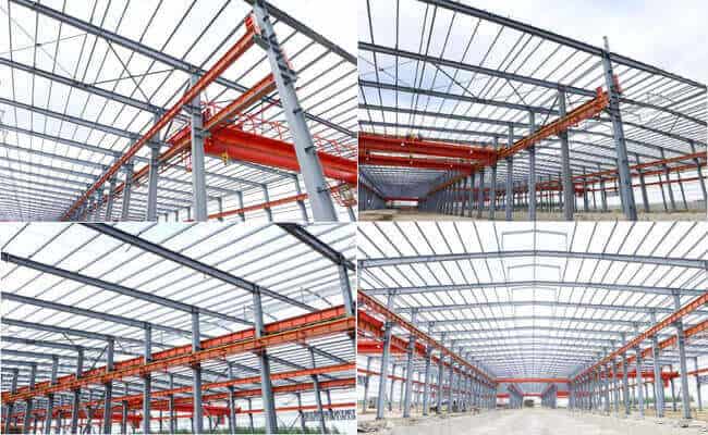
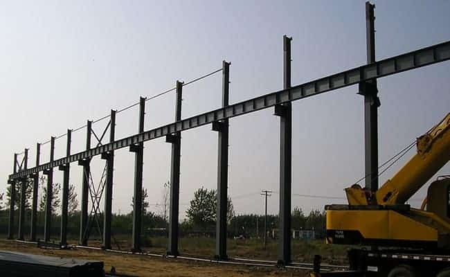
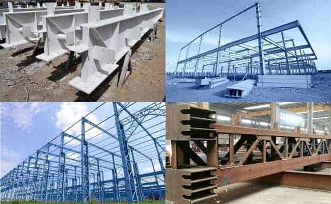
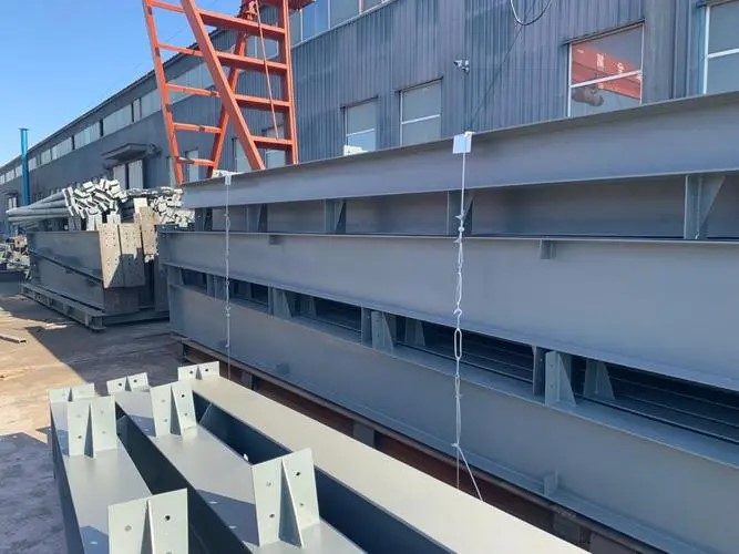
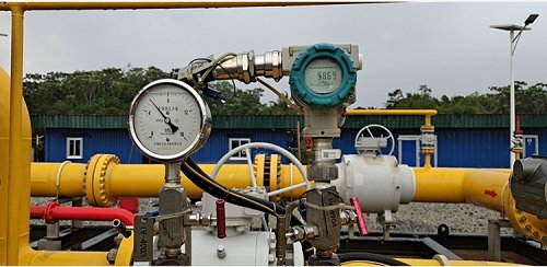
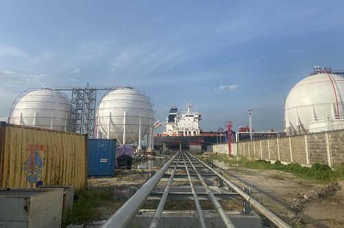
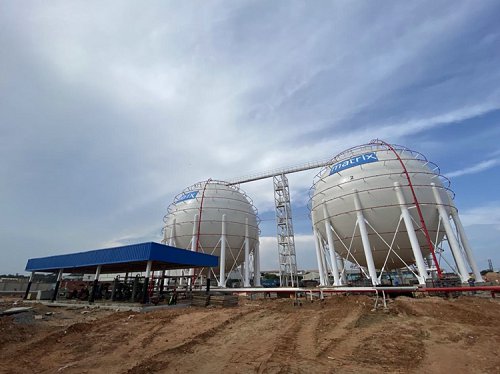
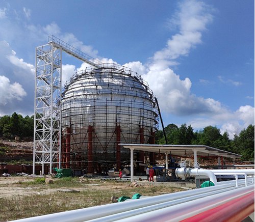
Our scope of works in this project main comprised of the followings:
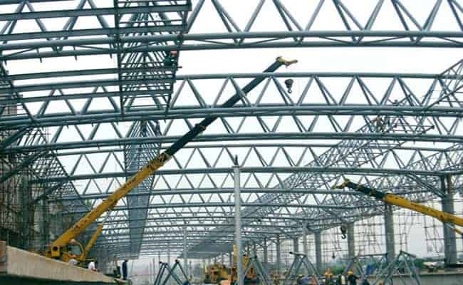
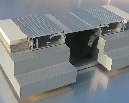
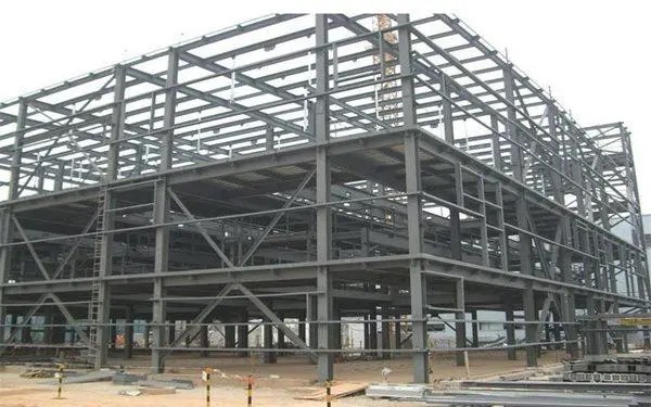
1. Natural Gas Conditioning and processing Plant Equipment platform structural steelworks;
2.LNG tanks
3. LNG tank foundation formworks (Prefabricated steel plate formworks);
4. Various site workshops(maintenance, chemicals, fabrication,plateworks,storage,warehouses) with overhead cranes;
5. kilometers of pipe racks and LNG equipment processing platforms;
Project execution period: May,2023 to April 2024.
The followings are the progress photos of the production and constructions of this projects:
General: Site general status photos(in progress):
The completion of this project will help the Client get a head start in the local LPG market and accelerate the energy transition from oil to gas in the industry. In addition, with the increasing awareness of sustainable development and carbon neutral among people, the project is also an exercise for ZHM's strategy for "Green Development and Green Supply Chain." With more LPG projects completed, ZHM is making its own contributions to the fight against climate change and the goal of carbon neutral.
Old Project Construction Memory